Initial testing
+/-9V supplies are ok but chip gets hot.
3.3V logic ok
SPI bus at 32MHz ok, at 35MHz it drops commands.
Weird way of working
Need to send reset to get chip going, probably syncing SPI bus etc
First send address
Then set MOSI pin to the state we want (which requires us to disable the SPI bus)
Turn on and off strobe for 10ns.
Tested
Mixing two inputs
Signal 3Hz to 35kHz tested ok
Inputs:
Input 1 (internal 0 and 1) ok
Input 2 (internal 2 and 3) ok
Input 3 (internal 4 and 5) ok
Input 4 (internal 6 and 7) ok
Input 5 (internal 8 and 9) ok
Input 6 (internal 10 and 11) ok
Input 7 (internal 12 and 13) ok
Input 8 (internal 14 and 15) ok
Outputs:
Sum A and B ok sums inputs correctly
FX A and B ok, sums inputs correctly
Crosstalk
Visible crosstalk between FX A and B, particularly when input is not connected to anything. Lowerst when input (in 8/internal 15 during testing) is connected to Bus A, more when connected to Bus B
Output til Bus A:
- Crosstalk on FX A: -9.7 to 37.5mV, avg 23.6mV
- Crosstalk on FX B: 1.49 to 22.4mV, avg 10.5mV
Output til Bus B:
- Crosstalk on FX A: -35.9 to 69mV, avg 52.45
- Crosstalk on FX B: -3.7 to 22.4mV, avg 13.2
Input not connected to output:
- Crosstalk on FX A: -56.9 to 90mV, avg 73.45
- Crosstalk on FX B: -19.4 to 38mV, avg 28.7
Crosstalk på Bus A/Bus B:
When everything is off
- Bus A: -22.3mV to 13.8mV, avg 18.1mV
- Bus B: -9.5 to 11.3mV, avg 10.4mV
When other bus is on
- Bus A: -12.0 to 3.5mV, avg 7.75mV
- Bus B: 9.45 to 11.3mV, avg 10.4mV
When output is to FX A and FX B:
Crosstalk on bus A and B looks a bit higher
Tried switching Bus A to input 1 with 33k to gnd, no improvement.
NB: Resolution of the logic probes is around 6mV
If one assumes an input of 2.5V, the highest crosstalk is (90--57)/2=74mV, so signal to crosstalk is attenuated 33 times (i.e. 3% of input). This corresponds to -30dB. Not impressive I think?
I cannot find any info about crosstalk in the CH446Q datasheet, but the MT8816 (which is sort of compatible) has a crosstalk between -45dB (for 2Vpp sine with freq 10MHz) and -85dB (for 10kHz)
-85dB corresponds to a V_in/V_crosstalk ratio of 0.0001
That would mean an input of +/-2.5V would result in crosstalk of 0.25mV
-45dB corresponds to a V_in/V_crosstalk ratio of 0.0056
That would mean an input of +/-2.5V would result in crosstalk of 14mV
This is not that far off from what we see when the input goes to one of the output busses. The max crosstalk is when the input is just blocked.
PS: In the tests above we always have TWO input signals, as every input is split in two. That means that even when one is passed, the other one is blocked. And when both are blocked, we get the same signal contributing to crosstalk twice.
Next to test:
- Is crosstalk the same if power is +/-5V as +/-9V?
- Is crosstalk reduced when we only have ONE copy of a signal?
- What is the crosstalk if we sink all non-used inputs to an output?
- Is the crosstalk the same if I switch to a new mixer board that was not heated as much by accident (!).
- What is the crosstalk on a DG412 (said to be -85dB, with -65dB offness to switch
- And not least, am I able to hear 75mV crosstalk at all? Especially when whatever it passes will be sent to the other filter and probably in some form to the output.
CH446X on breadboard
Testing with direct input of 3.5V, dropped through a 47k resistor before the switch, which gives the same current through the switch as the 2.5V/33k input of the bus mixer circuit.
Switching between Y0 (pin 43) and Y3 (pin 42), connected to an inverting opamp (47k in feedback).
Crosstalk
Only one input used, resistor before switch so 0 voltage at switch:
Y0: crosstalk is mostly 0.9-6.1mV (avg 2.6mV) with some jumps to as much as -4/16mV. 2.6mV/3600mV = -63dB, which is close to the offness of the DF412 switches)
Y3: crosstalk is mostly 11-16-mV (avg 2.5mV) with some jumps to as much as 0.7/32mV
Only one input used, resistor after switch so full voltage swing at switch:
This does not work at all! No idea why.
Only one input used, 1.2k resistor before and 47k after switch, almost all of the voltage swing is across the switch:
Crosstalk is now -25mV to 53mV or avg 39mV
Now something is wrong: It seems that the chip locks up and is not able to start properly, supply lines are not +/-5V and it draws a LOT of current. I managed to get it started again once, but after moving around resistors it locked up again.
To test I removed all ground connections from X-inputs. I just read that I should have done the opposite: "CMOS switches and multiplexers are symmetrical devices; their signal input and output terminals are interchangeable, so unused ones should all be considered to be inputs, not outputs. Thus, they should all be grounded."
Also, read this: https://www.ti.com/lit/an/scda011/scda011.pdf?ts=1693203318955&ref_url=https%253A%252F%252Fwww.google.com%252F
I re-added the gnd connections on all unused X and Y inputs, but nothing works. I will order a socket and try with an unused CH446X.
Second try, bus mixer
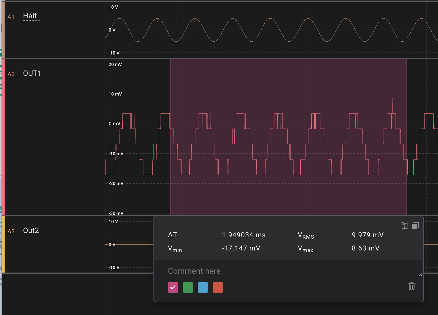
I went back and tried the bus mixer again. I didn't see as much crosstalk this time. Here we see input 0 going to output 2, 3 and 6 (FX A, FX B and SUM A) then pause for 200mS. For FX A and SUM A crosstalk is +/-6mV, while FX A has a crosstalk of +/-12mV.
Input is +/-10V going through a 33k/33k voltage divider so the bus mixer sees +/-5V at the input. This is amplified to +/-7.3V at the outputs, so any crosstalk is in relation to this. Right now, we see 6mV crosstalk on 7.3, which is around 61dB. That's ok I think.
Current consumption
The CH446Q and op amps on the mixer board runs rather hot, so I checked the current consumption without the AS3364 installed. The measurements include the op amp on the FX outputs which is external to the board. I got:
- 24mA on the 12V input
- 45-55mA on the -12V input (changing up and down. 45 when no output is on, 55 when one or more outputs are on).
A second mixer board, that has not had the output fix for bus wiring, and has never had any power issues, runs at around 23mA on the -12V input (as well as 24mA on the +12V input), which seems much more correct. Also, it doesn't fluctuate as much.
A TL07x op amp typically consumes 1.4mA. I have 8 of them, which should account for 11.2mA approx, leaving 12.8mA for the crosspoint switch, including some loss at the voltage regulators. It doesn't sound entirely unreasonable. I need to compare this to what DG412 uses.
Full bus mixer
I added two AS3364 quad vca chips and tested the control signals with 0 and 5V (though not anything in between). It worked flawlessly, though the output is perhaps +/- 0.2V below unity gain.
The current usage with two AS3364 is 37mA (+12V) and 55-69mA (-12V), so roughly 10mA more on each supply
Working program
#include <SPI.h>
#include "stdint.h"
#define PIN_CH446Q_STROBE 4
#define PIN_CH446Q_RESET 21
void setup() {
pinMode(PIN_CH446Q_STROBE, OUTPUT);
pinMode(PIN_CH446Q_RESET, OUTPUT);
pinMode(11, OUTPUT);
digitalWriteFast(PIN_CH446Q_STROBE, LOW);
digitalWriteFast(PIN_CH446Q_RESET, LOW);
delay(1);
digitalWriteFast(PIN_CH446Q_RESET, HIGH);
delay(1);
digitalWriteFast(PIN_CH446Q_RESET, LOW);
}
void setSwitch(uint8_t in, uint8_t out, uint8_t on){
uint8_t address = out * 16 + in;
// We need to use begin and end to regain control of the pin
// after the address is transfered, without this we cannot
// set the switch mode.
// 32MHz is the highest stable speed I was able to make work.
SPI.begin();
SPI.beginTransaction(SPISettings(32000000, MSBFIRST, SPI_MODE0));
SPI.transfer(address);
SPI.end();
// After writing the address, we need to set the MOSI pin to the
// wanted state of the switch, 0 for off and 1 for on, before
// strobing the strobe.
pinMode(11, OUTPUT);
digitalWriteFast(11, on);
// Strobe makes the switch... switch.
digitalWriteFast(PIN_CH446Q_STROBE, HIGH);
delayNanoseconds(20);
digitalWriteFast(PIN_CH446Q_STROBE, LOW);
}
void loop() {
setSwitch(0, 6, 1);
delay(500);
setSwitch(1, 6, 1);
delay(500);
setSwitch(0, 6, 0);
delay(500);
setSwitch(1, 6, 0);
delay(500);
}